Flip-Flops in Computer Organinsation
- Flip-flops are digital circuits that store binary information.
- Flip Flops can change state based on input signals, representing 0 or 1.
- Flip-flops are fundamental digital electronic circuits used in a wide range of applications.
Types of Flip-Flops
1. S-R Flip-Flop (Set-Reset Flip-Flop)
- The S-R flip-flop has two inputs: Set (S) and Reset (R).
- It can store one bit of information.
- When S=1 and R=0, it's in the set state (Q=1), and when S=0 and R=1, it's in the reset state (Q=0). If both S and R are 0, the output remains unchanged.
Example: Think of a light switch – when you flip it up (S=1), the light turns on (Q=1), and when you flip it down (R=1), the light turns off (Q=0).
For better understanding watch this video tutorial
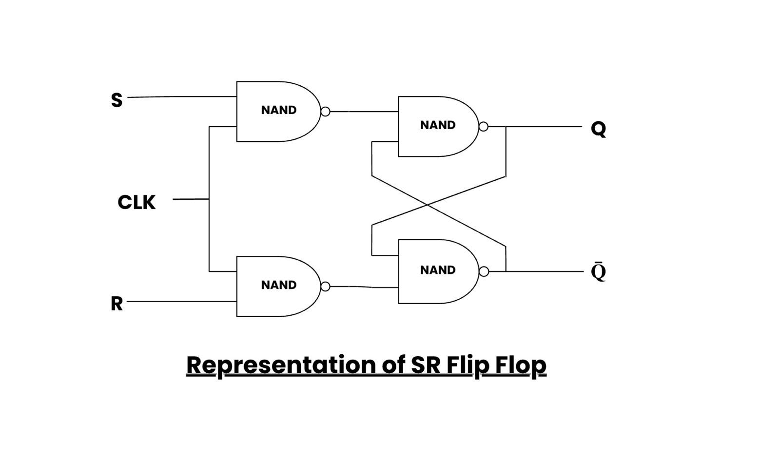
Representation of SR Flip Flop
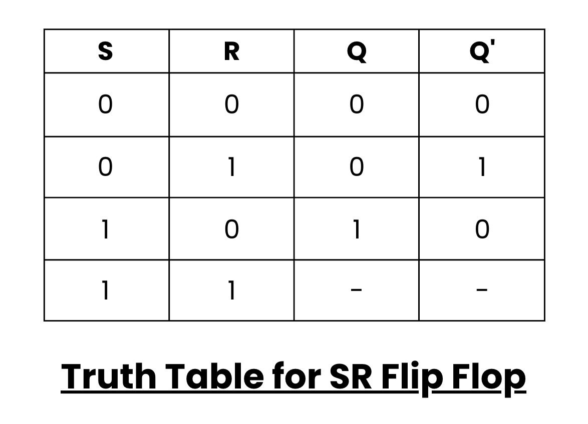
Truth Table for SR Flip Flop
2. D Flip-Flop (Data or Delay Flip-Flop)
- The D flip-flop has one input (D) and a clock signal (C).
- It stores the value of D at the rising or falling edge of the clock, depending on the type of D flip-flop.
- When C transitions, the flip-flop captures the value of D and holds it until the next clock transition.
Example: Imagine a mailbox with a flag. When you put a letter in (D=1) and raise the flag (C transition), it stays up until you lower it, just like the flip-flop holds the value.
For better understanding watch this video tutorial
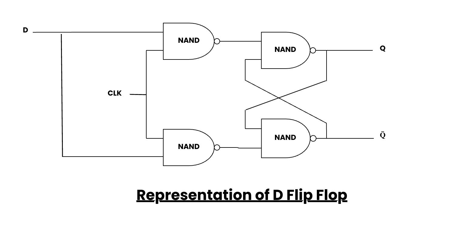
Representation of D Flip Flop
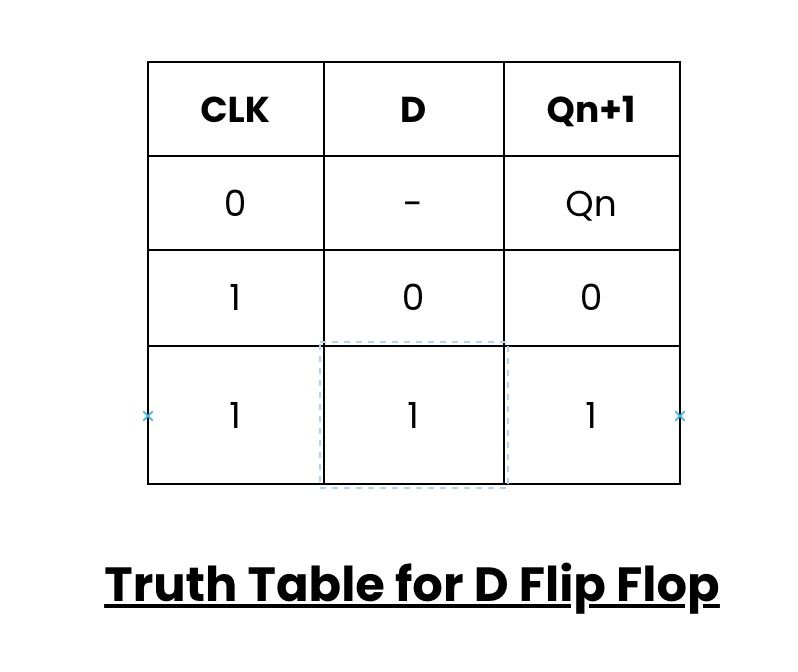
Truth Table for D Flip Flop
3. J-K Flip-Flop (Jump-Kill Flip-Flop)
- The J-K flip-flop has two inputs (J and K) and a clock signal (C).
- It can toggle its output Q or maintain its state based on the values of J and K during a clock transition.
Example: Think of a toggle switch – if you press "J" (set) and "K" (reset) simultaneously, it will toggle (flip) the state.
For better understanding watch this video tutorial
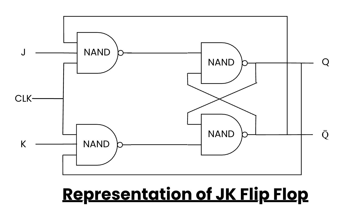
Representation of JK Flip Flop
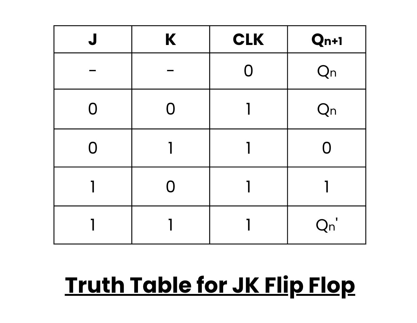
Truth Table for JK Flip Flop
4. T Flip-Flop (Toggle Flip-Flop)
- The T flip-flop has a T input and a clock signal (C).
- It toggles its output Q when T is 1 during a clock transition, and it remains unchanged when T is 0.
Example: It's like a light switch that flips (toggles) the light on and off each time you press it.
For better understanding watch this video tutorial
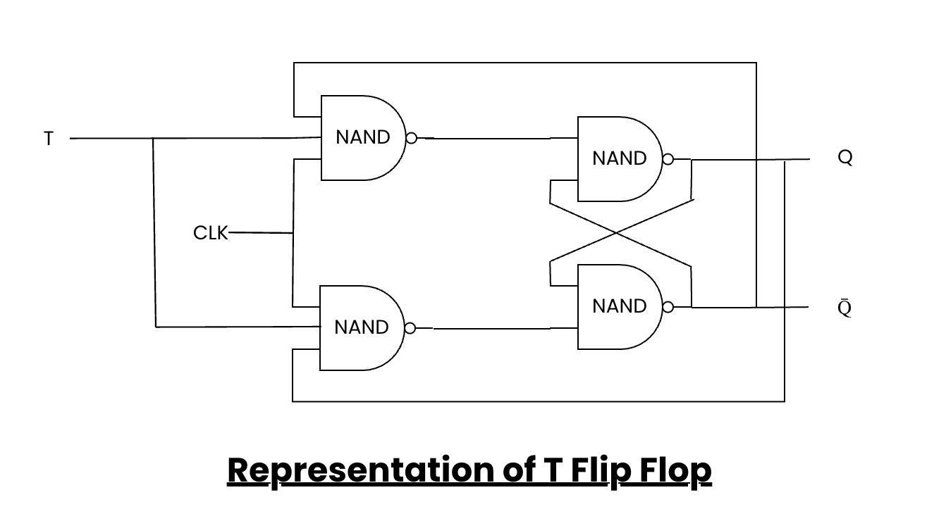
Representation of T Flip Flop
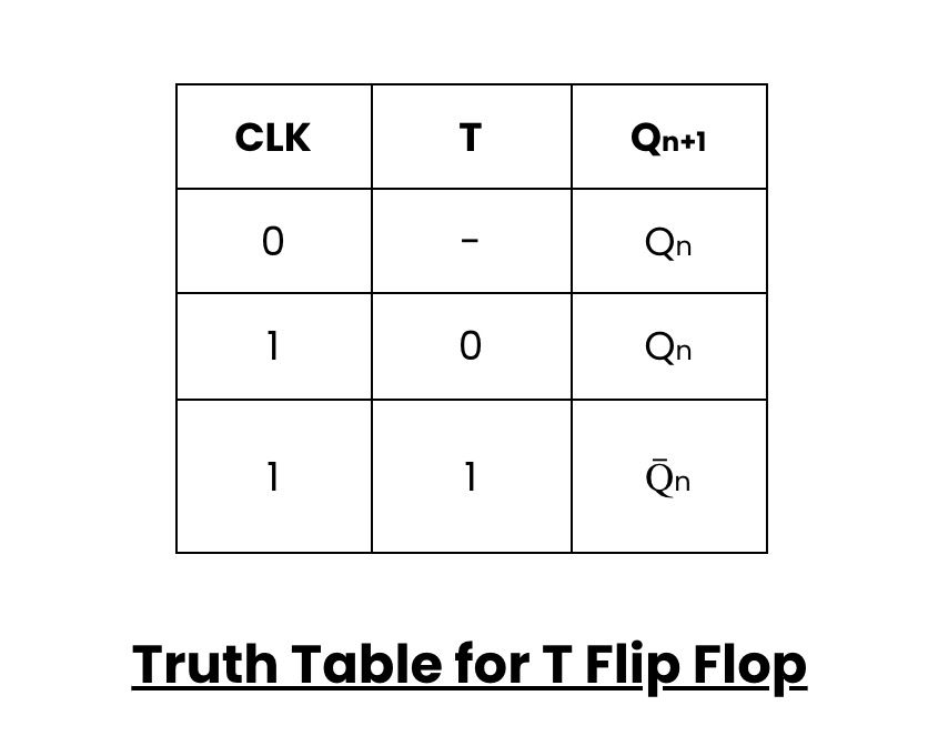
Truth Table for T Flip Flop
5. Clocked Flip-Flop
- A clocked flip-flop is a generic term for flip-flops with a clock input.
Examples include the D, J-K, and T flip-flops, which require a clock signal to operate. The clock synchronizes their actions.
Race Around Condition
- In digital circuits, a "race around condition" occurs when inputs change so quickly that the flip-flop's output becomes uncertain.
- It's like trying to catch a moving target. To avoid this, engineers use clock signals and proper timing.
For better understanding watch this video tutorial
Master-Slave Flip-Flop
- A master-slave flip-flop is a combination of two flip-flops.
- The first (master) latches the data during one phase of the clock signal, and the second (slave) latches it during the opposite phase.
- This ensures stable operation even with fast-changing inputs.
Realization of One Flip-Flop Using Another
- Engineers can design one type of flip-flop using another.
- For example, a J-K flip-flop can be built using two D flip-flops and some logic gates.
- This flexibility allows for efficient use of components in various applications.
1. Latches
- Latches are like simpler flip-flops. They are used for temporary storage, like holding data in a processor until it's processed.
Example: A door latch holds the door closed until you turn the handle to open it.
2. Registers
- Registers are groups of flip-flops used to store multiple pieces of data. They are the memory units in processors and digital devices.
Example: Think of a register as a row of mailboxes, each holding different letters (data).
3. Counters
- Counters are circuits that use flip-flops to count events. They're commonly used in digital clocks and timers.
Example: Your car's odometer is like a counter, keeping track of the number of miles you've driven.
Conclusion
- In conclusion, flip-flops are the building blocks of digital electronics, storing and manipulating binary data in various ways.
- Understanding their types, functions, and applications is essential for anyone interested in electronics or digital systems.